Fluorescent Tube Circuit Diagram

Fluorescent Light Wiring Diagram Tube Light Circuit Circuitstune

Tube Light Connection Diagram

Schematic Diagram Of The Uvc Fluorescent Light Circuit Installed In

Fluorescent Lamp Wikipedia

Light Circuit Diagram On Fluorescent Tube Light Circuit Diagram 2

Fluorescent Table Lamp Wiring Diagram Wiring Diagram Box

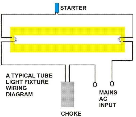
Fluorescent tube light circuit.
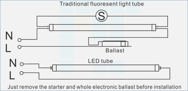
Fluorescent tube circuit diagram. A fluorescent lamp or fluorescent tube is a low pressure mercury vapor gas discharge lamp that uses fluorescence to produce visible light. Back to sams f lamp faq table of contents. After so many crt monitors sent in for repair i could say that i only came across one unit of a 14 acer monitor that had an open winding in the filament heater. When we connect the ac supply voltage to the circuit then the starter act like short circuited and current flow through those filament located at the first and second end of the tube light and the filament generate heat and it ionized the gas mercury.
Optimization of the circuit matching designoptimize the performance of the electrical design of the tube. Although an led tube light and a fluorescent tube work in different ways theoretically an led tube light is produced to replace a fluorescent tube under the similar shape and measurements. An electric current in the gas excites mercury vapor which produces short wave ultraviolet light that then causes a phosphor coating on the inside of the lamp to glow. Fluorescent fixture wiring diagrams wiring for preheat fluorescent fixtures the following is the circuit diagram for a typical preheat lamp one that uses a starter or starting switch.
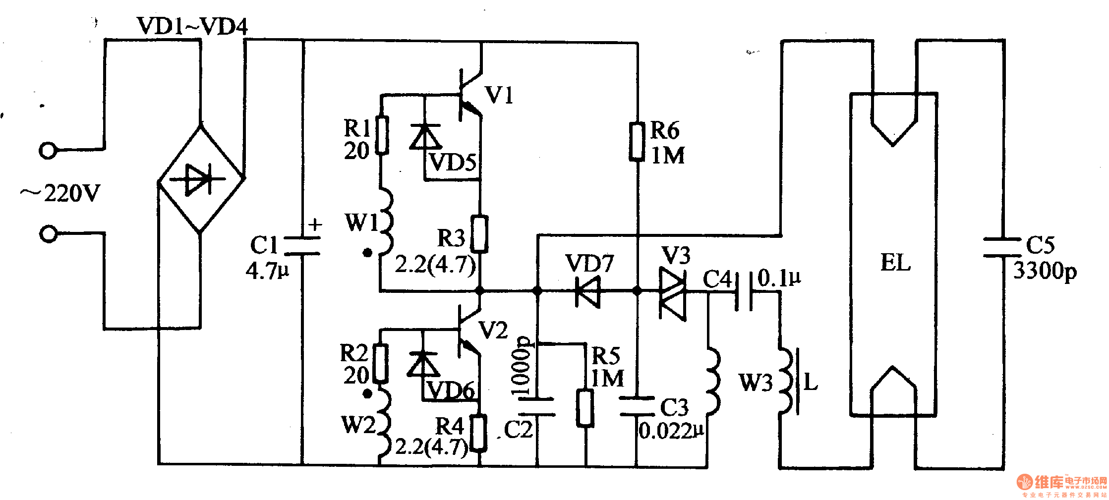
Most recent update on linked sites 1152019. The starter is like a key of fluorescent light because it is used to light up the tube. This type inverter can be made in various ratings such as 6v 10 watts. This tube light inverter circuit uses a single transistor and a single transformer.
Its behavior has been described many times in the literature and on the web so here ill only give a quick overview just to clarify what im talking about. Most recent update anywhere in this site other than notes of progress in linked sites 3102019.
How Do Fluorescent Tube Lights Work Explanation Diagram Included

Start It Up How Fluorescent Lamps Work Howstuffworks
Fluorescent Lamp Wikipedia
Fluorescent Inverter

Fluorescent Table Lamp Wiring Diagram Wiring Diagram Box

Light Ballast Wiring Diagram 3 12 Danishfashion Mode De

Wiring Multiple Fluorescent Light Fixtures 1 9 Petraoberheit De

Wiring Diagram For Led Fluorescent Light Wiring Diagram

Circuit Diagram Electronic Ballast Tube Light 20 16 Danishfashion

2 Ballast Wiring Diagram 14 13 Petraoberheit De
Circuit Diagram Electronic Ballast Tube Light 20 16 Danishfashion
Wiring Diagram For T8 Led Tube Light 18 13 Petraoberheit De

Why Does A Fluorescent Lamp Need A Choke Coil To Work Quora
