Fluorescent Tube Wiring Diagram

Double Tube Light Circuit Diagram

Fluorescent Light Wiring Diagram Tube Light Circuit Circuitstune

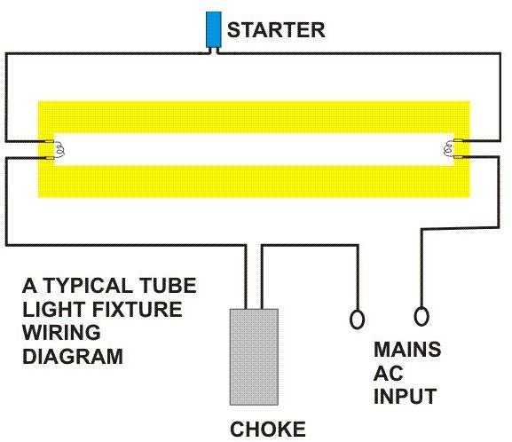
Tube Light Connection Diagram
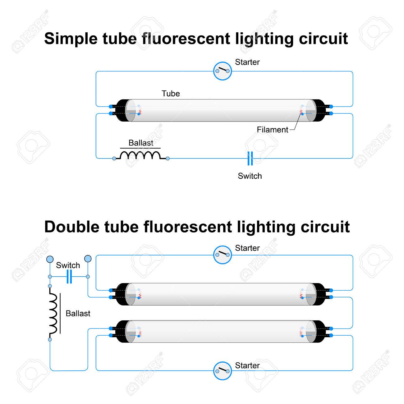
Single And Double Tube Fluorescent Lighting Circuit Simple Vector

Wiring Diagram For A Single Tube Light Circuit Electrical4u

Wiring Diagram For A Single Tube Light Circuit Electrical4u

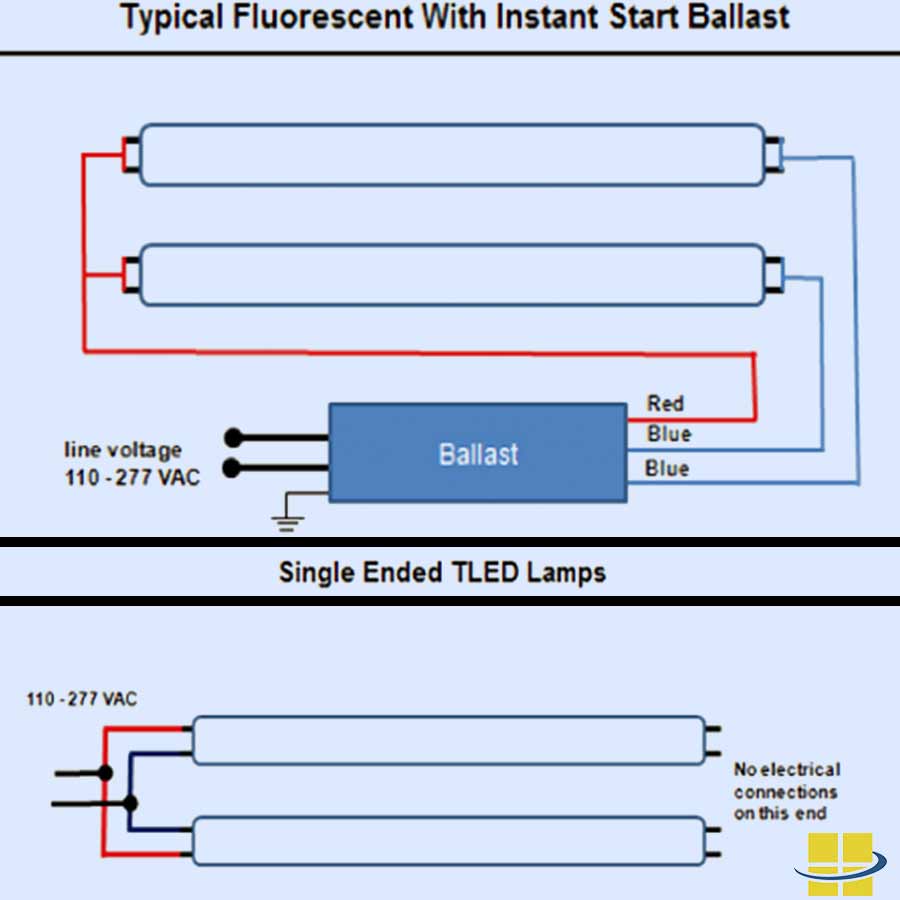
Wiring diagrams and descriptions to help you understand fluorescent ballasts including series and parallel ballasts.
Fluorescent tube wiring diagram. An electric current in the gas excites mercury vapor which produces short wave ultraviolet light that then causes a phosphor coating on the inside of the lamp to glow. No returns no refunds. And at the bottom that shows capacitor connection diagram of ceiling fan. Various electronic fluorescent tube lamp ballast.
This tube light inverter circuit uses a single transistor and a single transformer. Fluorescent light wiring diagram tube light circuit this is about how to wiring fluorescent light and how a fluorescent tube light works. This type inverter can be made in various ratings such as 6v 10 watts. 1 this product must be installed by a professional or qualify individual with knowledge of applicable installation codes.
Most recent update on linked sites 1152019. This is a simple wiring diagram of ceiling fan. Most recent update anywhere in this site other than notes of progress in linked sites 3102019. Fluorescent tube light circuit.
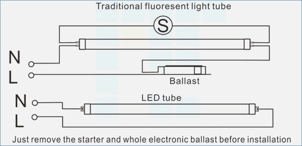
A fluorescent lamp or fluorescent tube is a low pressure mercury vapor gas discharge lamp that uses fluorescence to produce visible light. Although an led tube light and a fluorescent tube work in different ways theoretically an led tube light is produced to replace a fluorescent tube under the similar shape and measurements.
How Do Fluorescent Tube Lights Work Explanation Diagram Included

Fluorescent Table Lamp Wiring Diagram Wiring Diagram Box

Fluorescent Light Fixture Ballast Wiring Diagram 17 11

8 Foot Fluorescent Light Wiring Diagram Wiring Diagram Box
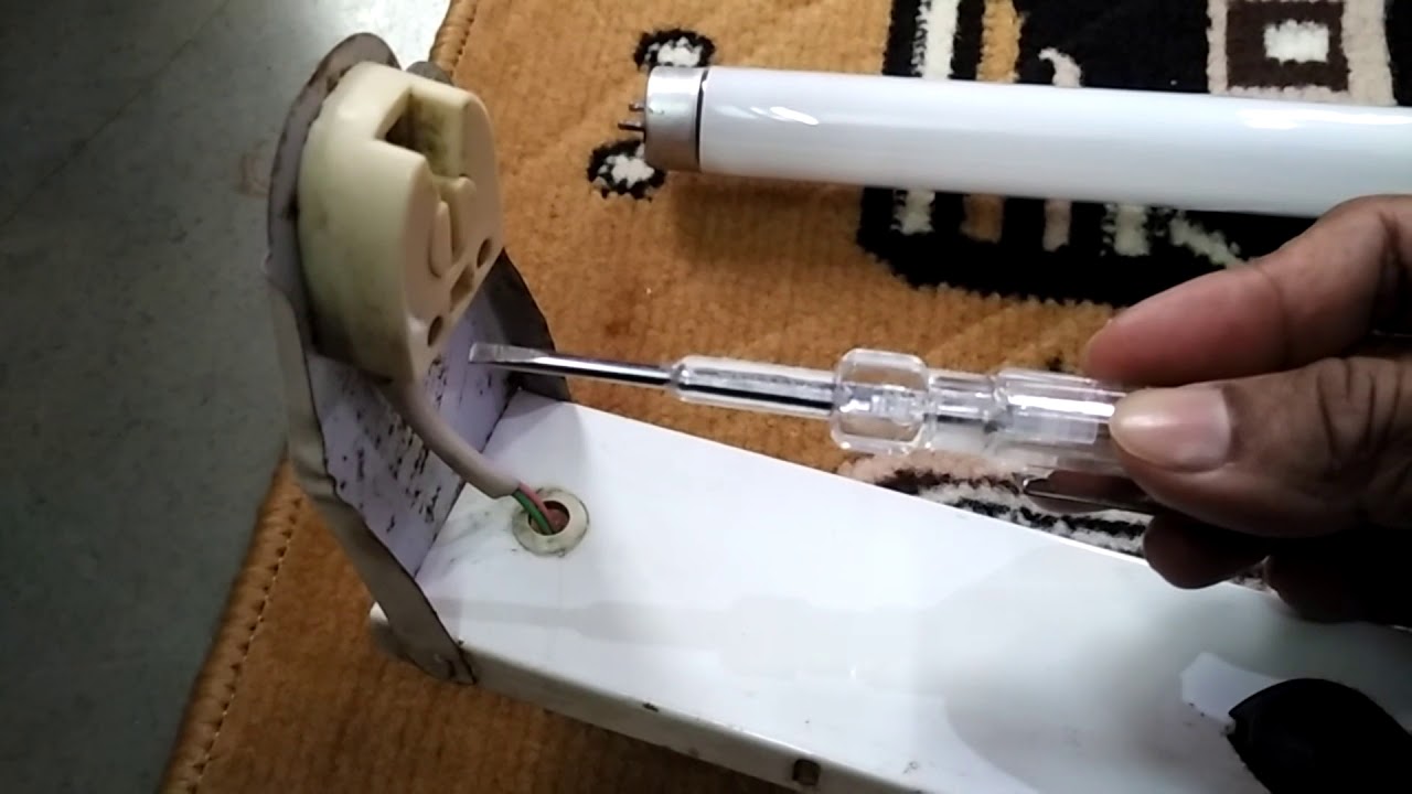
How To Make Fluorescent Tube Light Wiring Connection With Circuit

Fluorescent Table Lamp Wiring Diagram Wiring Diagram Box

Wiring Diagram For T8 Led Tube Light 18 13 Petraoberheit De
Tombstone Fluorescent Lights Wiring Diagram 20 11 Danishfashion

Light Ballast Wiring Diagram 3 12 Danishfashion Mode De

Wiring Diagram For T8 Led Tube Light 18 13 Petraoberheit De
Fluorescent Lamps Ballasts And Fixtures
Wiring Diagram For T8 Led Tube Light 18 13 Petraoberheit De

Wiring Diagram For Led Fluorescent Light Wiring Diagram
