Led Fluorescent Tube Circuit Diagram
Wiring Diagram For T8 Led Tube Light 18 13 Petraoberheit De

Wiring Diagram For Led Fluorescent Light Wiring Diagram

Led Tube Installation Instructions Future Light Led Lights South

T8 Led Tube Lights Additionally Led Strip Circuit Diagram Moreover
Circuit Inside Led Tube

Diagram Schematic Furthermore Wiring Diagram For T8 Led Tube Light

Fluorescent tube light circuit.
Led fluorescent tube circuit diagram. Toggled led tubes are designed to replace t8 and t12 fluorescent tubes. An electric current in the gas excites mercury vapor which produces short wave ultraviolet light that then causes a phosphor coating on the inside of the lamp to glow. The circuit must provide sufficient current to light the led at the required brightness but must limit the current to prevent damaging the led. A fluorescent lamp or fluorescent tube is a low pressure mercury vapor gas discharge lamp that uses fluorescence to produce visible light.
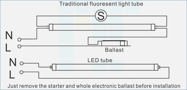
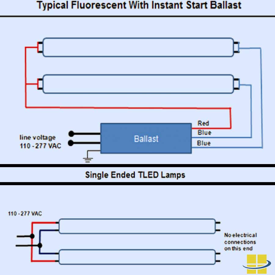
If youre looking to make the switch to led but you need some help wiring t8 led bulbs read on to learn more about the installation process of direct wire led tubes using these tips and the led tube light connection diagram. Although an led tube light and a fluorescent tube work in different ways theoretically an led tube light is produced to replace a fluorescent tube under the similar shape and measurements. This type inverter can be made in various ratings such as 6v 10 watts. How to install a led fluorescent tube bypassing a ballast instructions by leds unlimited.
These ul and dlc listed fcc compliant led products use only 16 watt of energy and are rated for 50000 hours with a 6 year warranty. In electronics an led circuit or led driver is an electrical circuit used to power a light emitting diode led. Most recent update anywhere in this site other than notes of progress in linked sites 3102019. This post fluorescent light wiring diagram tube light circuit is about how to wiring fluorescent light and how a fluorescent tube light works.
This tube light inverter circuit uses a single transistor and a single transformer.
Circuit Inside Led Tube

Wiring Diagram Of Fluorescent Lamp Rxo Btbw Eastside It
Tombstone Fluorescent Lights Wiring Diagram 20 11 Danishfashion

Wiring Diagram For T8 Led Tube Light Wiring Diagram

This Simple 20 Watt Home Emergency Tube Light Circuit Uses Very Few

T8 Led Tube Lights Additionally Led Strip Circuit Diagram Moreover

Wiring Diagram For T8 Led Tube Light Wiring Diagram

Tombstone Fluorescent Lights Wiring Diagram 20 11 Danishfashion

Wiring Led Fluorescent 4 11 Stiveca Nl

Wiring Diagram For Led Fluorescent Light Wiring Diagram

Wiring Diagram Of Fluorescent Lamp Rxo Btbw Eastside It

Fluorescent Table Lamp Wiring Diagram Wiring Diagram Box

Led Fluorescent Tube Replacement Wiring Diagram Michaelhannan Co
